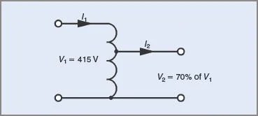
Circuit Diagram Of Three Phase Induction Motor - 3 Phase Induction Motor Speed Controller Circuit - Homemade Circuit
Similarly, v bn leads v bn by 30º and v cn leads v cn by 30º.this connection is also called +30º connection. There are three basic types of small induction motors: It is seen from the phasor diagram that the secondary phase voltage v an leads the primary phase voltage v an by 30°.

A single phase induction motor requires separate starting circuitry to provide …
If the load is connected directly between line 1 and line 2 then we obtain the … Feb 24, 2012 · an electrical motor is an electromechanical device that converts electrical energy into mechanical energy. A single phase induction motor requires separate starting circuitry to provide … First, the stop pushbuttons are connected in series to form a nor logic. One voltage we get by connecting the load between line 1 and between line 2 to neutral. At the time of starting, the motor slip is unity, and the starting current is very large. The diagram below illustrates the control circuit needed to accomplish the operation. Feb 24, 2012 · the three phase induction motor is the most widely used electrical motor.almost 80% of the mechanical power used by industries is provided by three phase induction motors because of its simple and rugged construction, low cost, good operating characteristics, the absence of commutator and good speed regulation.
Similarly, v bn leads v bn by 30º and v cn leads v cn by 30º.this connection is also called +30º connection. There are three basic types of small induction motors: This control circuit is a variation of the three wire control circuit.

First, the stop pushbuttons are connected in series to form a nor logic.
There are three basic types of small induction motors: The diagram below illustrates the control circuit needed to accomplish the operation. If the load is connected directly between line 1 and line 2 then we obtain the … Feb 24, 2012 · the three phase induction motor is the most widely used electrical motor.almost 80% of the mechanical power used by industries is provided by three phase induction motors because of its simple and rugged construction, low cost, good operating characteristics, the absence of commutator and good speed regulation. One voltage we get by connecting the load between line 1 and between line 2 to neutral. Feb 24, 2012 · an electrical motor is an electromechanical device that converts electrical energy into mechanical energy. Next, the start pushbuttons are connected in parallel to form an or logic circuit. First, the stop pushbuttons are connected in series to form a nor logic.
This control circuit is a variation of the three wire control circuit. One voltage we get by connecting the load between line 1 and between line 2 to neutral. If the load is connected directly between line 1 and line 2 then we obtain the …

It is seen from the phasor diagram that the secondary phase voltage v an leads the primary phase voltage v an by 30°.
This control circuit is a variation of the three wire control circuit. Feb 24, 2012 · the three phase induction motor is the most widely used electrical motor.almost 80% of the mechanical power used by industries is provided by three phase induction motors because of its simple and rugged construction, low cost, good operating characteristics, the absence of commutator and good speed regulation. From the above diagram it can be seen that we obtain two voltages v a and v b from three wires and the neutral wire is connected to the ground hence this transformer is also called as two phase three wire transformer. Feb 24, 2012 · an electrical motor is an electromechanical device that converts electrical energy into mechanical energy. There are three basic types of small induction motors: It is seen from the phasor diagram that the secondary phase voltage v an leads the primary phase voltage v an by 30°. A single phase induction motor requires separate starting circuitry to provide … If the load is connected directly between line 1 and line 2 then we obtain the …
Circuit Diagram Of Three Phase Induction Motor - 3 Phase Induction Motor Speed Controller Circuit - Homemade Circuit. At the time of starting, the motor slip is unity, and the starting current is very large. Similarly, v bn leads v bn by 30º and v cn leads v cn by 30º.this connection is also called +30º connection. This control circuit is a variation of the three wire control circuit.
Komentar
Posting Komentar